Introduction
In earlier articles we have covered a number of techniques for documenting and designing the static behaviour of systems. We saw one way of representing dynamic behaviour when we looked at State-Transition diagrams [ Blundell98 ], but these diagrams only really deal with a single object at a time. [ 1 ] This month we shall look at collaborating objects and their interactions over time. The charts we will use are useful for documenting real-time systems as well as for complicated processes involving many calls between the objects involved.
Interactions
Conceptually, objects interact by exchanging messages . A message is typically 'sent' using a normal function call, but can also be sent as an inter-thread or inter-process signal, or an event triggered by a hardware device or operating system interrupt such as a timer. An interaction is a set of message exchanges that collectively achieve some purpose, usually one that represents some higher-level action. In other words, an interaction is the collection of inter-object messages that produces some outcome.
In system design and documentation, it is a common requirement to document the (non-trivial) interactions of a system, and there are two types of Interaction diagram with which this can be done - Collaboration diagrams and Sequence diagrams .
Collaborations
A collaboration is a set of objects involved in completing some action or operation, combined with the interaction that produces the action. The collaboration contains only those objects that are involved in the action (or actions - a collaboration can describe several related or even unrelated operations or interactions).
Collaboration Diagrams
Collaboration diagrams document collaborations. Visually, a collaboration diagram looks like an object diagram, complete with associations between the objects shown in the normal way. On top of this diagram are superimposed an ordered set of message flow arrows showing the pattern of messages that form the interaction. A simple example is shown in figure 1.
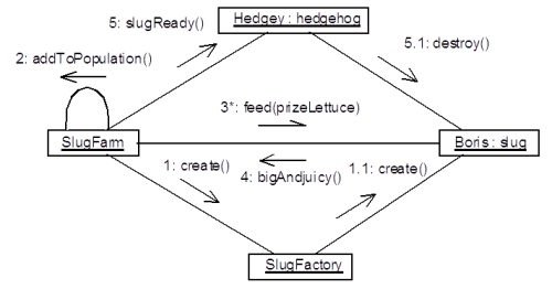
Figure 1. A collaboration diagram showing the creation of a slug in a slug farm, and its ultimate consumption, after fattening, by a hedgehog.
A message flow shows the transfer of a message from one object to another. A short arrow is used to denote a message flow. Typically, the arrowhead is solid, indicating sequential or nested operation as is used in normal single-threaded procedural design. A half stick arrowhead is often used to denote asynchronous calls. If an object sends a message to itself (to show iteration, for example) the arrow can follow a self-association line, as shown in step 2 of the figure (and can optionally be labelled with the stereotype «self»). Each arrow can be labelled with a set of expressions that show details of the messages, and the conditions under which the message is sent.
Simple message flows are labelled with a sequence number and a message name, possibly with a return type. For example:
1.1.4: ret := process(arg, …)
The sequence number is the part before the first colon. Sequence numbers show the order in which the message flows occur. The number of decimal points shows the call depth. In the above example, this message flow is the fourth at the current nesting level, and is nested three levels deep. An example numbering scheme can be seen in the figure. After the colon, we have the return value, name of the message, and argument list for the message.
There are several extensions to this basic syntax. A guard condition can be added (in square brackets) before the sequence number to show a conditional message. The message is only sent if the condition is true:
[t > last] 1.3: update()
As well as digits, letters can be used in a sequence 'number' to show concurrent threads. Thus, a step 1.2 could be followed by 1.2.1a and 1.2.1b, showing that it passes control to two threads.
Before the guard condition, another form of condition can be added that shows the predecessor of the message flow. This is a list of sequence numbers of messages (followed by a forward slash) that must all have occurred before the current message will fire. This allows threads to be synchronised by requiring different threads to all have reached some designated point:
1.4a,1.2b/ 2: theyveFinished()
Here, message 2 is only sent after the first thread has sent message 1.4a, and the second thread has sent 1.2b.
Branches and iteration can be shown by appending a recurrence term (in square brackets) after a sequence number. An example of a branch would be message labels such as 1.1[t = t0] and 1.1[t < > t0], and the message actually sent depends upon the value of t. If the recurrence conditions are mutually exclusive (as here), then a single procedural branch is suggested. If the conditions overlap, concurrent sequence numbers can be used to show the start of multi-threaded processing. Iteration is shown using an asterisk and an expression showing the details of the iteration, for example 2.5*[i := 0..n-1]. In this example, the labelled message fires n times in succession.
The lifetime of an object in a collaboration can be shown using the stereotypes «new», and «destroyed», with «transient» meaning a combination of the two. Sometimes these are shown as constraints in curly braces instead of stereotypes. As we shall see later, object lifetimes can be shown more explicitly on sequence diagrams.
Design patterns are collaborations (plus additional information such as examples of use, limitations, usage guidelines, etc.), and as such can be partly documented using collaboration diagrams. Once a pattern has been documented and named, it can be shown on diagrams using the dashed-oval representation described in an earlier article [ Blundell97 ], with the actual objects that enact the pattern bound to the roles within the pattern definition.
That is pretty much it for collaboration diagrams. A normal static structure diagram with message flows to show the interactions that occur. [ 2 ] Collaboration diagrams are useful because they show not only the sequence details of the interaction, but also its full context - which objects are involved and how they are related. The disadvantage of these diagrams is that for complicated interactions they can become very cluttered and difficult to interpret.
Sequence Diagrams
Sequence diagrams are the second type of interaction diagram, and these primarily show the interaction details, omitting much of the information about the collaboration. The objects involved in the interaction are shown, but no relationships are given. To offset this restriction, however, the time-order of the message flows and object lifetimes are much more obvious, and very involved interactions are much simpler to interpret.
A typical sequence diagram has time down the page, and individual objects laid out across the top of the diagram, as shown in figure 2. Lifelines for each object are drawn as vertical dashed lines. The lifeline begins at the top of the page or at the point that the object is created in the interaction, if later. The lifeline stops at the bottom of the diagram, or at the point of a large X where the object is destroyed, if earlier. Message flows are shown as horizontal arrows [ 3 ] from one object to another, and the messages are laid out in time-order down the diagram. Conditional (or concurrent) behaviour can be shown using multiple message arrows, each labelled with a guard condition. Target lifelines can split in two to show alternative or parallel scenarios, with a recombination possible further down the page.
A feature known as focus of control can be added to diagrams to show the intervals over which each object is 'active' in the sense that it is either processing itself or waiting for another object to finish processing (sometimes these two cases are distinguished by shading the box (described next) in the former case). When an object is active, its lifeline temporarily becomes a long thin box. Recursive calls are shown by drawing an additional activation box offset from the main one. The depth of nesting can be shown by multiple offset boxes if you care to go to that much effort!
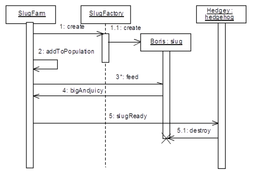
Figure 2. A sequence diagram corresponding to the collaboration diagram in figure 1. The slug farm, slugs and hedgehogs each have their own thread, so I have shown their focus of control boxes as continuously active (assuming they do other processing in the background), whereas the factory is only active when the create method is called by the farm.
As with collaboration diagrams, message flows can be labelled with guard conditions, message name, arguments, etc. Sequence numbers are usually omitted in single-threaded interactions because the sequence of messages is shown explicitly by the ordering of the arrows. In addition, returns from procedure calls can be shown using dashed return arrows.
Conclusion
Over the months we have seen how to document some of the static and dynamic details of a system. State-Transition diagrams are useful for describing the behaviour of a single class, but to document collaborating objects the Sequence and Collaboration diagrams (collectively called Interaction diagrams) described above are very handy. Next time I'll go back to the design stage taking a look at Use Cases and Use Case diagrams, and see how these can be used to define the scope and behaviour of a system.
References
[Blundell98] "UML - State Transition Diagrams", Overload 24 pp 2 - 5
[Blundell97] "UML - Objects and Patterns", Overload 23 p 6
[ 1 ] Although of course that object can be an aggregation of other objects, or a system or subsystem with conceptual 'states'.
[ 2 ] A few other capabilities include showing active objects with a heavy border to their rectangular symbol, and nesting objects within others.
[ 3 ] … in the case of messages that can be considered to be instantaneous. If there could be a significant delay in the receipt of the message, and if this delay could mean the sequence of messages could be interrupted, a downward-slanted arrow can be used to show this.